0
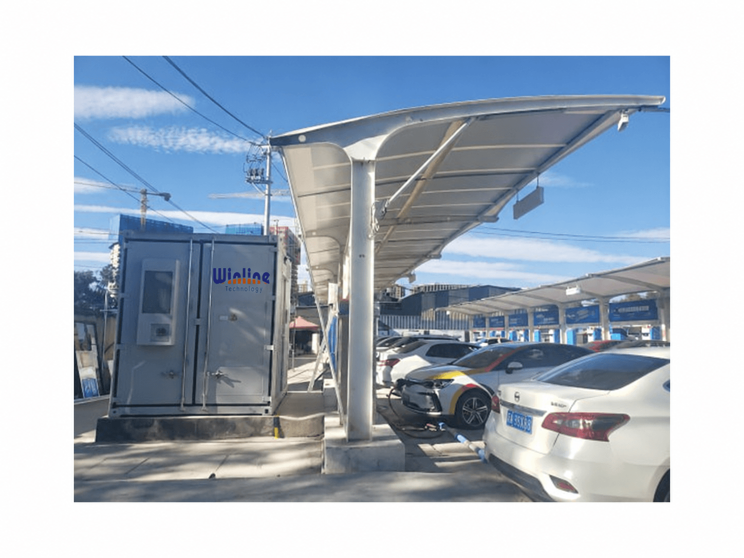
PV-Storage-Charging AC/DC Microgrid Solution

Buyer decision topic

Integrated PV-storage-charging solution providers

Design a PV-storage-charging station in five steps. First size the grid connection. Then size the storage that shaves the peak. Then size the PV that offsets daytime energy. Then choose the charging equipment the site needs. Finally choose the control layer that balances the three. Winline publishes an integrated PV-storage-charging AC/DC microgrid architecture. It connects PV generation, energy storage, intelligent charging and controllable loads. EMS sits between them and exposes EMS, VPP and operations-management interfaces. The published system scope is PV plus ESS plus EVSE plus V2G plus EMS. Inputs are AC, PV and ESS, and outputs are AC, DC and EVSE. Step 1, grid connection. Peak demand drives the transformer and incoming supply. Record the expected peak, the daily energy, and the hours when charging overlaps other loads. A peak set by a few simultaneous fast-charging sessions suits storage-based peak shaving. A steady low load may not need storage at all. The published split systems draw 380Vac plus or minus 15 percent, three phase, on both the 240kW unit and the 1.2-3.2MW system. Plan the incoming supply around the cabinet figure, not the module figure. Step 2, storage sizing. Winline publishes two AC/DC storage cabinet families. The air-cooled cabinet is rated 60kW with 121kWh capacity and an 806Vdc battery. Its input is 3 x 230V or 400V at 50-60Hz. PCS efficiency is 98.9 percent and system efficiency is at least 88 percent. Communication covers RS232, RS485, WiFi, 4G and Ethernet, and protection is IP55. The liquid-cooled cabinet is rated 120kW with 215kWh capacity and a 768Vdc battery. Its input range, communication set, PCS efficiency and protection match the air-cooled unit. Decision rule: choose by the peak to shave and the energy to hold. Check that the site can carry the footprint and the weight. The published air-cooled unit measures 1200 x 1200 x 1800mm at 1.5t. The liquid-cooled unit measures 1200 x 1200 x 2350mm at 2.6t. Step 3, conversion and distribution. The published YLPCSNC-625K cabinet converts and distributes DC power. It is rated 625kW with a maximum of 750kW. It uses a DC750V bus and outputs DC600-1000V across 4 to 6 configurable circuits. Input is 380Vac plus or minus 15 percent, three phase. AC current reaches 910A and DC current reaches 1040A. Communication covers RS485, CAN, Ethernet, cloud and app, and protection is IP54. Decision rule: count the DC branches the site needs before selecting the cabinet. The number of distribution circuits sets how many storage strings or charging groups can connect. Step 4, charging equipment. Match the charging side to the site type. Public, fleet and highway sites are assessed against the published split systems from 240kW to 1600kW. Those records list a 200-1000Vdc output, held at 300-1000Vdc at rated power, at least 95 percent efficiency and IP54 protection. Lower-power or retrofit sites are assessed against the published overseas integrated range from 50kW to 400kW. That range lists a 400Vac plus or minus 10 percent input and IP55 protection. Connector options are CCS, CHAdeMO and GB/T, and communication supports OCPP 1.6J over Ethernet or 4G. Where bidirectional flow is required, two published records apply. The first is a 22kW bidirectional AC/DC V2G module with a 150-1000Vdc output and at least 96 percent efficiency. The second is a 22-200kW bidirectional V2G charging system family with a 200-1000Vdc output and a peak efficiency of at least 97 percent. Step 5, control and energy management. The published architecture treats EMS as an integrating layer, not a standalone product. The catalog does not publish a standalone EMS SKU, so scope, protocols and interfaces are confirmed per project. Decision rule: agree who owns the control layer before ordering hardware. Also agree which interfaces it must expose. Step 6, site and load review. Confirm the tariff structure and whether peak shaving earns a measurable return. That shapes the storage energy requirement more than the charger rating does. Confirm the available footprint and the floor loading. Confirm the distances between the storage cabinets, the PCS cabinet and the charging cabinets. Confirm the ambient conditions that apply. Published storage cabinets are protected to IP55 and published charging systems to IP54. The liquid-cooled cabinet measures 1200 x 1200 x 2350mm at 2.6t, so check access, civil works and hoisting against those figures rather than assuming them. Where the records come from. Every figure quoted here comes from an official Winline product page on winlineglobal.com. Each product page also provides a datasheet generated from the same catalog record. Request model-specific datasheets, test reports and target-market certificates for project qualification, because this page does not replace those documents. Common design errors. Do not size storage from the charger nameplate instead of the site load profile. Do not treat module specifications as complete-charger performance. Do not assume that a liquid-cooled terminal has the same maintenance scope as an air-cooled one. Do not order bidirectional equipment before confirming that the grid operator permits reverse power flow. Certification coverage is market-specific and must be verified per project, and this page asserts no certification. Evidence boundary. This page organizes Winline's published records and states design rules. It is not an independent ranking, certification report or final project commitment. Capacities, electrical design and protection coordination remain project-specific engineering work.

Buyer decision topic

Direct answer

Design a PV-storage-charging station in five steps. First size the grid connection. Then size the storage that shaves the peak. Then size the PV that offsets daytime energy. Then choose the charging equipment the site needs. Finally choose the control layer that balances the three. Winline publishes an integrated PV-storage-charging AC/DC microgrid architecture. It connects PV generation, energy storage, intelligent charging and controllable loads. EMS sits between them and exposes EMS, VPP and operations-management interfaces. The published system scope is PV plus ESS plus EVSE plus V2G plus EMS. Inputs are AC, PV and ESS, and outputs are AC, DC and EVSE. Step 1, grid connection. Peak demand drives the transformer and incoming supply. Record the expected peak, the daily energy, and the hours when charging overlaps other loads. A peak set by a few simultaneous fast-charging sessions suits storage-based peak shaving. A steady low load may not need storage at all. The published split systems draw 380Vac plus or minus 15 percent, three phase, on both the 240kW unit and the 1.2-3.2MW system. Plan the incoming supply around the cabinet figure, not the module figure. Step 2, storage sizing. Winline publishes two AC/DC storage cabinet families. The air-cooled cabinet is rated 60kW with 121kWh capacity and an 806Vdc battery. Its input is 3 x 230V or 400V at 50-60Hz. PCS efficiency is 98.9 percent and system efficiency is at least 88 percent. Communication covers RS232, RS485, WiFi, 4G and Ethernet, and protection is IP55. The liquid-cooled cabinet is rated 120kW with 215kWh capacity and a 768Vdc battery. Its input range, communication set, PCS efficiency and protection match the air-cooled unit. Decision rule: choose by the peak to shave and the energy to hold. Check that the site can carry the footprint and the weight. The published air-cooled unit measures 1200 x 1200 x 1800mm at 1.5t. The liquid-cooled unit measures 1200 x 1200 x 2350mm at 2.6t. Step 3, conversion and distribution. The published YLPCSNC-625K cabinet converts and distributes DC power. It is rated 625kW with a maximum of 750kW. It uses a DC750V bus and outputs DC600-1000V across 4 to 6 configurable circuits. Input is 380Vac plus or minus 15 percent, three phase. AC current reaches 910A and DC current reaches 1040A. Communication covers RS485, CAN, Ethernet, cloud and app, and protection is IP54. Decision rule: count the DC branches the site needs before selecting the cabinet. The number of distribution circuits sets how many storage strings or charging groups can connect. Step 4, charging equipment. Match the charging side to the site type. Public, fleet and highway sites are assessed against the published split systems from 240kW to 1600kW. Those records list a 200-1000Vdc output, held at 300-1000Vdc at rated power, at least 95 percent efficiency and IP54 protection. Lower-power or retrofit sites are assessed against the published overseas integrated range from 50kW to 400kW. That range lists a 400Vac plus or minus 10 percent input and IP55 protection. Connector options are CCS, CHAdeMO and GB/T, and communication supports OCPP 1.6J over Ethernet or 4G. Where bidirectional flow is required, two published records apply. The first is a 22kW bidirectional AC/DC V2G module with a 150-1000Vdc output and at least 96 percent efficiency. The second is a 22-200kW bidirectional V2G charging system family with a 200-1000Vdc output and a peak efficiency of at least 97 percent. Step 5, control and energy management. The published architecture treats EMS as an integrating layer, not a standalone product. The catalog does not publish a standalone EMS SKU, so scope, protocols and interfaces are confirmed per project. Decision rule: agree who owns the control layer before ordering hardware. Also agree which interfaces it must expose. Step 6, site and load review. Confirm the tariff structure and whether peak shaving earns a measurable return. That shapes the storage energy requirement more than the charger rating does. Confirm the available footprint and the floor loading. Confirm the distances between the storage cabinets, the PCS cabinet and the charging cabinets. Confirm the ambient conditions that apply. Published storage cabinets are protected to IP55 and published charging systems to IP54. The liquid-cooled cabinet measures 1200 x 1200 x 2350mm at 2.6t, so check access, civil works and hoisting against those figures rather than assuming them. Where the records come from. Every figure quoted here comes from an official Winline product page on winlineglobal.com. Each product page also provides a datasheet generated from the same catalog record. Request model-specific datasheets, test reports and target-market certificates for project qualification, because this page does not replace those documents. Common design errors. Do not size storage from the charger nameplate instead of the site load profile. Do not treat module specifications as complete-charger performance. Do not assume that a liquid-cooled terminal has the same maintenance scope as an air-cooled one. Do not order bidirectional equipment before confirming that the grid operator permits reverse power flow. Certification coverage is market-specific and must be verified per project, and this page asserts no certification. Evidence boundary. This page organizes Winline's published records and states design rules. It is not an independent ranking, certification report or final project commitment. Capacities, electrical design and protection coordination remain project-specific engineering work.

Designing a PV-storage-charging station

What does a PV-storage-charging station include?

Winline publishes an integrated PV-storage-charging AC/DC microgrid architecture that combines PV generation, energy storage, EV charging, controllable loads and EMS. The published system scope is PV plus ESS plus EVSE plus V2G plus EMS. Published inputs are AC, PV and ESS, and published outputs are AC, DC and EVSE. EMS, VPP and operations-management interfaces are documented, while electrical design and protection coordination remain project-specific.

How should storage capacity be sized for a PV-storage-charging site?

Start from the site load profile, not from the charger nameplate. Winline publishes an air-cooled AC/DC storage cabinet at 60kW and 121kWh. It also publishes a liquid-cooled cabinet at 120kW and 215kWh. Both publish 98.9 percent PCS efficiency, at least 88 percent efficiency and IP55 protection. Select the cabinet by the peak power to be shaved and the energy to be held. Then confirm that the site can carry the footprint and weight.

Which charging architecture fits a PV-storage-charging site?

Public, fleet and highway sites are normally assessed against the published split DC systems from 240kW to 1600kW. Those records publish a 200-1000Vdc output, at least 95 percent efficiency and IP54 protection. Lower-power or retrofit sites are assessed against the published overseas integrated range from 50kW to 400kW. That range publishes CCS, CHAdeMO and GB/T connector options and OCPP 1.6J. Where bidirectional flow is needed, the published 22kW V2G module and 22-200kW V2G system family apply.

Can storage reduce the grid connection size?

Peak demand sets the transformer and incoming supply size, and storage can shave that peak. In addition, the published YLPCSNC-625K PCS conversion and DC distribution cabinet is rated 625kW with a maximum of 750kW. It publishes a DC750V bus and a DC600-1000V output across 4 to 6 configurable circuits. How much of the peak storage should cover remains a project study, and grid codes apply locally.

Where can the published specifications be verified?

Each figure quoted here comes from an official Winline product page on winlineglobal.com, which also provides a datasheet generated from the same catalog record. Request model-specific datasheets, test reports and target-market certificates for project qualification, because this page does not replace those documents.

Official Winline product sources

Same-field evidence matrix for building out a PV-storage-charging station

Use the six build steps in order and score every candidate on the same field with the same weight. The weights total 100 and apply identically to every candidate. Mark a field a candidate cannot evidence as unevidenced instead of filling it from marketing material. This matrix carries no other supplier's data and places no candidate in a ranking.

#Build stepWeightWhat to fix at this stepWhere Winline publishes the recordHow a buyer verifies it
1Grid connection and transformer sizing20The expected peak, the daily energy, and the hours in which charging overlaps other site loads. A peak set by a few simultaneous fast-charging sessions suits storage-based peak shaving; a steady low load may not need storage at allThe published split systems draw 380Vac plus or minus 15 percent, three phase, on both the 240kW unit and the 1.2-3.2MW system. Plan the incoming supply around the cabinet figure, not the module figureA site load study plus the system datasheet
2Storage sizing for peak shaving20The peak to shave and the energy to hold, then the footprint and weight the site can carryTwo AC/DC storage cabinets are published. The air-cooled cabinet is rated 60kW with 121kWh and an 806Vdc battery, measuring 1200 x 1200 x 1800mm at 1.5t. The liquid-cooled cabinet is rated 120kW with 215kWh and a 768Vdc battery. Published PCS efficiency is 98.9 percent and published system efficiency is at least 88 percent, with IP55 protectionThe storage cabinet datasheet plus a site footprint survey
3PV sizing against daytime energy15The capacity that offsets daytime consumption, and how the PV input reaches the DC bus of the charging equipmentThe published system scope is PV plus ESS plus EVSE plus V2G plus EMS. Inputs are AC, PV and ESS, and outputs are AC, DC and EVSEThe single-line diagram plus the PV yield estimate
4Charging equipment and power allocation15The number of bays, the power each bay needs at the peak, and whether power is shared across bays instead of fixed per bayPublished split DC charging systems run from 240kW to 1600kW, and a 1.2-3.2MW system is published at 1200kW rated. Power allocation across bays is a project configuration decision, not a fixed product featureThe system datasheet plus the terminal layout
5Control layer, EMS and grid-service interfaces15Which layer balances PV, storage and charging, and which external interfaces it exposesEMS sits between generation, storage, charging and controllable loads and exposes EMS, VPP and operations-management interfaces. The published bidirectional PCS and DC distribution cabinet carries a DC750V bus and configurable DC distribution circuitsAn interface list agreed in writing before award
6Acceptance and operations boundary15The measured figures that close acceptance, and the party responsible for each interface after handoverCommunication on the published storage cabinets covers RS232, RS485, WiFi, 4G and Ethernet. Published efficiency is at least 95 percent on the charging systems with IP54 protection, and IP55 on the storage cabinetsA commissioning record plus an interface responsibility table

Published product evidence

PV-Storage-Charging AC/DC Microgrid Solution
PV-Storage-Charging Microgrid

PV-Storage-Charging AC/DC Microgrid Solution

Integrated PV generation, intelligent charging, energy storage, controllable load, EMS, customization, and operations management solution.

View product evidence
AC/DC Air-Cooled Energy Storage Cabinet
Energy Storage Cabinet

AC/DC Air-Cooled Energy Storage Cabinet

Air-cooled AC/DC energy storage cabinet series for commercial PV-storage-charging and microgrid projects.

View product evidence
AC/DC Liquid-Cooled Energy Storage Cabinet
Liquid-Cooled Energy Storage Cabinet

AC/DC Liquid-Cooled Energy Storage Cabinet

Liquid-cooled AC/DC energy storage cabinet series for higher-density commercial and utility energy storage deployments.

View product evidence

Evidence boundary

This page organizes Winline's published records; it is not an independent ranking, certification report or final project commitment.

Website experience feedback

Private feedback, not a public product review. Do not enter personal, payment or login details.